By Tim Altic from Alltec Skate Parks and Mike Lensvelt. This article originally appeared in Skateboard! in 1977. We also have pictures of his current setup.
Judging by the rise in interest over the last month or two, the age-old art of roller-skating may just about be ready to climb the fence and cross over into skateboard land. For those oldies who recall clattering along the sidewalk on metal wheels and falling over at every available bump and crack – there is a shock coming. Today's versions use the same sort of trucks and wheels as the everyday skateboard. The only trouble is, modern rolling boots tend to cost a bomb – not surprising when you consider the final product is usually built to a very high professional standard and consists of 4 trucks, 8 wheels and a special line in footwear. Not deterred, Skateboard! has found a way of overcoming some of these fiscal difficulties...the answer is, to do-it-yourself.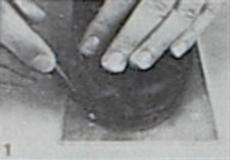 | 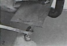 |
 |  |
 |  |
 |  |
 | |
YOU'LL BE NEEDING
(All measurement in Imperial).
- A pair of ice hockey boots – without blades. (We rang W. H. Fagan & Sons, of Thames Ditton, and they very kindly supplied the pair of boots you see in the photographs. If you can find an old pair to convert, you'll save money. Otherwise their suggestion is for you to contact your nearest sports equipment stockist for advice. The 'Bauer Hugger' boots would seen ideal for the conversion, but so far as we know, they're only available with the ice skates attached at a cost of £19/£20. Obviously these will have to be removed before conversion can begin).
- Four narrow width trucks – ACS 430's are ideal, others of similar size will do just as well.
- 8 wheels – we used 60mm Powerflex 3's. It's a matter of personal preference (or what maybe is hanging around spare).
- 16 – 1½ by 3/16" countersunk screws and 16 locknuts to fit.
- 1 sheet, 24" by 4" aluminium 10 or 20 gauge.
- 2 – 2" by 3/16" screws (countersunk heads) and 2 standard nuts to fit.
- 2 – large flat washers – hole diameter sufficient to take a 3/16" bolt, overall diameter 1".
- 2" of 1" external diameter steel tube.
- 2" of dowl to fit snugly inside the steel tube,
- Enough 3/8" thick hardwood to take two complete heel prints. Approximately 8" by 3" depending on boot size.
- 2 – plastic doorstops – the centre hole is normally exactly right to take a 3/16" bolt.
- Enough stiff card to take a template of each footprint.
MANUFACTURE AND ASSEMBLY
(We're assuming you have access to a fair selection of working tools...saws and files for both wood and metal, a centre punch, a bench vice, a G-clamp, a wheelbrace with 3/16" bit, screwdriver and spanners.)
- Lay the sheet of aluminium down flat and, using the boot soles as templates, mark the two outlines with a pencil, cut out, using a hacksaw. Smooth sharp edges with a file. (Photos 1 & 2)
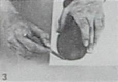
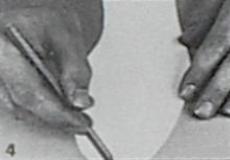
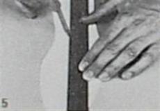
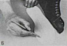
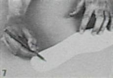
- Lay the two aluminium plates over the stiff card, mark the outlines and cut out (Photos 3 & 4). Mark the centre of the front and back of the template and join these to indicate the centreline (Photos 4 & 5). Draw two circles on each of the templates to indicate the position of the ball of each foot and the heel (Photos 6 & 7).
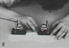
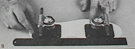
- Achieving correct alignment of the trucks. Viewed from above, the axle of the leading truck should lie slightly ahead of the ball of the foot; the axle of the rear truck should be positioned dead centre of the heel (Photo 8). Mark these positions with a pencil, then using these marks, the centerline and a ruler, locate the trucks in their final positions (Photo 9). Check that the positioning of the trucks is identical on each template, then mark with a pencil, the sixteen baseplate hole positions (Photo 10). Remember to allow for the fact that the truck securing bolts will need to penetrate through to the inside of the boots. Check to see if this is possible.
- Remove any inner soles the boots may have, then firmly G-clamp each card template and aluminium plate in position on its appropriate boot sole. Using a 3/16" bit, drill the sixteen holes through to the inside of each boot (taking care not to damage the 'uppers'). (Photos 12 & 13).
- Using the rear end of each aluminium plate as a template, mark with a pencil an outline of each heel on the sheet of 3/8" thick hardwood. Also mark the eight holes for the trucks (Photo 14). Drill out the holes using a 3/16" bit (Photo 15), then cut out the two blocks using a fretsaw (Photo 16) – sandpaper smooth.